top of page
Bell System Crossbar Exchange Family Tree
This section is a short review of the crossbar exchanges designed by Bell engineers and installed in the telephone plant from 1933 to 1978 (last install). It is presented as a genealogical "family tree" for exchanges. The tree has figurative branches and stems indicating where some inherited traits came from. There is a picture gallery with family portraits.
The crossbar office was also popular outside of North America but only the Bell family tree is considered for this coverage. There are more details on crossbar switches history/functionality and exchange workings elsewhere on this site.
Fig 1 divides the family tree into three branches: Small city (including unattended Community Dial Offices, or CDOs) along with the Private Branch Exchange (PBX for businesses), Local Metro offices (subscribers attached) and Toll offices (no subs attached). These three areas cover the broad domain of crossbar switching exchanges. Metro covers big city systems (end offices) and Toll covers long distance switching centers.
Not every crossbar system developed by Bell is included here. For example, numbers 1S, A4A, 4M, 300, 745A (one installed), 757, SS400 (both spawned from 756), and 812A are not covered. There is a crossbar class called Automatic Call Distributors (ACDs) also not considered. The workhorse no. 5 crossbar from 1948 until at least 1975 expanded its feature set. It went from about 50 features at introduction to about 750 features in 1975 [Joel, Fig 11-55].
The long distance network was comprised of a hierarchy of toll offices. The Toll article explains the purpose of the office classes, numbered 1 to 5. Local central office exchanges (of any switching type) are classed as a 5 and Toll offices are classed from 1-4. If you are not familiar with office classes, reviewing the Toll article will help understand Fig 1.
It should be noted that each office class could, in theory, be built from Panel, Step-by-Step, Crossbar or Electronic Switching Systems (ESS) equipment. A class type is mostly agnostic to its implementation. That said, Panel was not widely used in toll with Step finding a foot hold. Crossbar won in toll over time. Regarding call interop, see Endnote 2 in the toll article.

Fig 1, Crossbar exchange family tree
Associated with each office type is an image when available. See the gallery images below. Images are arranged based on Fig 1: from left column to right column, top to bottom.
To get a feeling for the symphony of sounds inside a switching exchange, explore Demo #3: audio soundscapes.
Crossbar Family Image Gallery

Fig 2, Schematic of no. 380 Crossbar, Community Dial Office (CDO) 1940 [Joel]

Fig 3, Installation of a 755A Crossbar PBX in NYC 1938 [Gray]

Fig 4, Front view of 756 Crossbar PBX 1956+ [Joel]

Fig 5, "No. 43" Crossbar Community Dial Office plan.
It was the inspiration for the no. 5 Crossbar office [Joel]
Figures 6A-6C below are courtesy of Phil McCarter from his personal #3 crossbar system.

Fig 6A, No. 3 Crossbar master test frame

Fig 6B, No. 3 Crossbar, one aisle

Fig 6C, No. 3 Crossbar, incoming register. Note the P1-P5 relays. These are part of the 5-digit dial pulse counting circuit. Note the 5 brass-colored "register relays" (each with 5 internal reed relays) for storing the 0, 1, 2, 4, 7 code. For example, a dialed 8 is coded as 7+1. This register records up to 5 dialed digits. See Fig 7 on the relay logic page for a similar design.

Fig 7A, No. 1 Crossbar, incoming frame group 1938 [Western, Fig 44]

Fig 7B, No. 1 Crossbar Block Diagram, greatly simplified [Survey]

Fig 7C, No. 1 Crossbar Maintenance frames [CMoS]
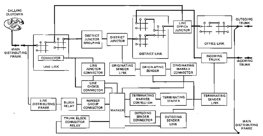
Fig 8, No. 2 crossbar, developed for small offices, never put into production [Joel]

Fig 9A, block diagram, No. 5 crossbar exchange for local subscriber switching [Adam]

Fig 9B, No. 5 crossbar Master Test Frame. Switches select test conditions and lamps indicate test results-- success or failure. [CMoS]

Fig 9C, Docent Ed Matson giving a no. 5 crossbar exchange tour at the Connections Museum of Seattle in 2017. Ed is explaining the purpose of the trouble ticket. This card is punched by a device that associated with the Master Test Frame.

Fig 9D, portions of the no. 5 crossbar exchange at the Connections Museum of Seattle. Each switch has 200 individual cross-points, with 6 "make" contacts at each intersection. The large connector relays on the right side (see Fig 9A) are activated to give a control Marker access to the crossbar's electromagnets and test points.

Fig 10A, block diagram of a Crossbar Toll Tandem office. Often called a XBT and is a derivative of the no. 1 Crossbar local office. This was only used to route calls inside the network. Endpoint subscribers were never directly connected to this office [Fundamentals].

Fig 10B, general view of main aisle Crossbar Tandem toll office [McCandless].
Many frames were nearly identical to the No. 1 Crossbar local office.

Fig 11A, Taken at the time of the #4 Crossbar toll office cutover in Philadelphia on August 22, 1943, this photograph shows, kneeling, J. E. Murdoch (left), Chief Engineer, Eastern Area, Bell of Pa., and A. B. Clark, Director of Systems Development, Bell Laboratories; standing, left to right, F. J. Chesterman, Vice-President, Operations, Bell of Pa.; C. H. McCandless, Switching Development, Bell Laboratories; and C. R. Freehafer, Vice-President and General Manager, Eastern Area, Bell of Pa. [Myers]

Fig 11B, The sender test frames (left) and the trouble indicator frames (right) of a No. 4 Toll office. [Bellows]
References
Adam, A.O., No. 5 Crossbar Marker, Bell Laboratories Record, November 1950
Bellows, B.C., Philadelphia adopts automatic toll switching, Bell Laboratories Record, November 1943
CMoS, Connections Museum of Seattle (working museum of #1, #5 crossbar, Panel, Step-by-Step and other exchange types)
Davis, R. C. "The Crossbar System." Bell Laboratories Record, February 1939. (#1 Crossbar)
Gray, C.R., The 755 PBX, Bell Laboratories Record, June 1938
Fundamentals of Telephone Communication Systems, Western Electric, 1969
Joel, A.E., A History of Engineering and Science in the Bell System Switching Technology, 1925-1975
McCandless and Collins, Crossbar Dial System, 1938, Bell Telephone Laboratories.
Myers, O., Markers for the Crossbar Toll System, Bell Laboratories Record, August 1944
Survey of Telephone Switching, compiled by staff of Pacific Telephone Co, 1956
Western Electric, The No. 1 Crossbar Dial Telephone System, Lesson 5, 1959 edition
bottom of page