
Exchange Structural Framing and Wiring
Most images of telephone exchange rooms depict consecutive rows of large switches and relay racks, mounted side-by-side on iron frames. Tying all this together is miles of connecting wiring. This section will describe some aspects of the structural framing and wiring for building an exchange. Of course, it's only a snapshot of the effort. One metric to be discussed may surprise you, “miles per foot”. The amount of iron and wire used to make an exchange come to life is astonishing.
Bay after bay
Fig 1 shows ~14 bays (Bell System naming), side-by-side, of #1 Crossbar equipment– relays, crossbar switches, cabinets, etc, with most wiring hidden behind the bays. Multiply this by 20 or so for a typical central office and you can appreciate the magnitude of the structure required to mount the components. Eleven foot tall, four foot wide iron bays were often used. Rolling aisle ladders were common for accessing the individual pieces for troubleshooting and repairs. See Figs 2-4 for other examples.


Fig 1, Typical bays in a #1 Crossbar system, 1938 [Xbar]
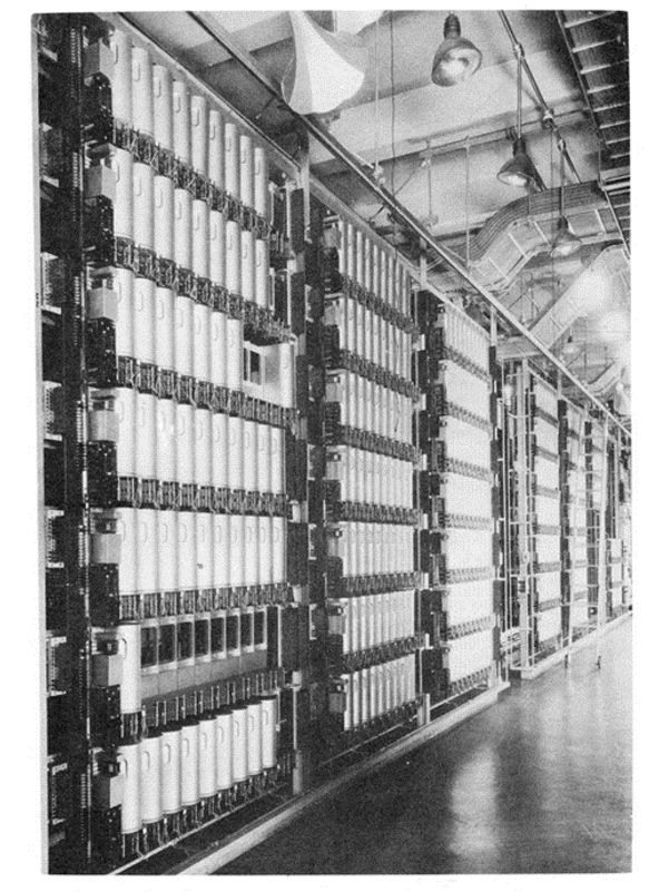
Fig 2, Typical equipment row of a Step-by-Step exchange 1937 [Step]
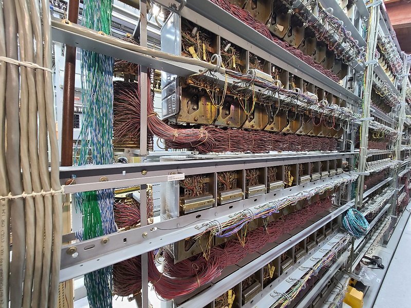
Fig 3. Framing and wiring for SxS switch banks (rear side)
-- Source [JKL]

Fig 4, Framing and wiring terminals associated with typical SxS exchange
-- Source [JKL]
Welders, take your stations
How much effort was needed to assemble a panel exchange in the 1930’s?
A 7-digit Panel installation took about two years with many installers (Fig 5). About 200 men would do the iron work first. Then about six months later 100 installers would do the assembly and wiring. So about 40% of the total installation effort was only for iron work! The first large-scale exchanges were a hardy mix of electro-mechanical components, wires, and iron frames.
[Panel]
Installing a SxS or Crossbar system was equally challenging with an abundance of frames and wiring. Many frames came from the factory prewired but there was much interconnecting wiring needed on site.

Fig 5
Wiring at one mile per foot
This subtitle is not a misprint. Imagine a single 4 foot wide panel-exchange bay using a mile of harness wire for every foot of its height!
As mentioned, individual exchange frames are wired at the factory and interconnected on site. Fig 6 shows a section of a particular panel frame’s wiring circa 1925. In total, eleven miles of wire, cut into 6,854 pieces, are needed to interconnect the coils, contacts, over four hundred relays, and other elements for just this one 11’ tall panel frame [Hance].

Fig 6, Wiring harness beauty [Hance]
While most panel exchange frames have a similar construction, this example from 1927 likely represents one of the more complex wiring configurations. Assuming an average panel bay uses say 5 miles of wire, with 70 frames in an exchange, 350 miles of wire would be needed.
Fig 7 shows the wiring harness (attached to a layout board) used to wire the apparatus in Fig 6.

Fig 7. Eleven miles of wiring harness for one bay [Hance]
More mountains of wire
To get a grand total we need to include the wiring between the frames and the wiring connecting the subscriber’s incoming lines (from the building’s cable vault) to the core switching frames. Fig 8 shows a main distribution frame (MDF). These are terminals for connecting the switching equipment (inside plant) to subscriber lines on poles (outside plant).
Adding it all together, there may be a few thousand miles of inside wiring to support 10K subscribers. Some large metro exchange buildings may house ten separate 10K line exchanges. So, one can only imagine the plexus of wiring for such exchange complexes.

Fig 8, Main Distribution Frame at C&P Telephone Co., 1905

Fig 9, Connective wiring of crossbar switches (top) and wire spring relays
The waxy cable lacing twine helps keep the wire routing organized.
Bottom line, exchanges are complex beasts. Together the framing, relays, switches, wires, and other elements form part of a large tapestry that is truly an engineering marvel.
References
Hance, P.D., “Eleven miles of wire”, Bell Laboratories Record, August 1927
JKL, Figs 3, 4. Thanks to Remco Enthoven, JKL Museum of Telephony, 2023
Panel, “The Last Panel System”- WE (Western Electric Magazine), First Quarter 1983 issue
Step, THE STEP-BY-STEP DIAL TELEPHONESYSTEM, 1937, Western Electric Co. publication
Xbar, THE NO. 1 CROSSBAR DIAL TELEPHONE SYSTEM, 1938 Western Electric Co. publication